EMGworks Compatibility NoticeEMGworks Acquisition and Analysis 4.8.0 was released in December 2021 and is now End of Life. Due to constantly evolving operating systems, hardware, and software dependencies, EMGworks may be incompatible with current releases of Windows operating systems and PC hardware. Please contact Delsys Support if you have questions and for best practices when installing EMGworks.
Getting Started
Installing EMGworks – What to expect and necessary requirements
The EMGworks Software installer contains the following programs and utilities:
EMGworks Acquisition
EMGworks Analysis
Trigno Control Utility (Software Development Kit Server)
Delsys File Utility
Delsys Software Update Tool
User Account Requirements:
EMGworks should be installed while logged in as an Administrator on the Windows PC. The program requires complete permission to access locations like the user AppData folder and Registry Editor.
Without proper admin permission to these locations, the installer may fail to complete. Please confirm the User Account privileges if EMGworks fails to install.
Recommended PC Specifications:
Windows 10, Windows 8, Windows 7 with service pack 3. 64-bit systems
At least 2.0 GHz processor clock speed (optimized for processors supporting SSE2 extensions)
At least 2 GB system memory
At least 128 MB discrete graphics memory
1280×1024 (SXGA) display resolution or better
Users can simply ensure that they have a Windows Experience Index of 4.0 or greater, in lieu of requirements 1 through 5
How is my data named and saved when using EMGworks?
The .hpf data files created when running EMGworks Acquisition are named according to the following guide.
Ex: Run_number_1_Plot_and_Store_Rep_1.
Test Run Name– Name of the overall test, which appears in each file for all upcoming tasks and repetitions. Users generally use a Subject ID or Experiment Name, although it is purely up to the user.
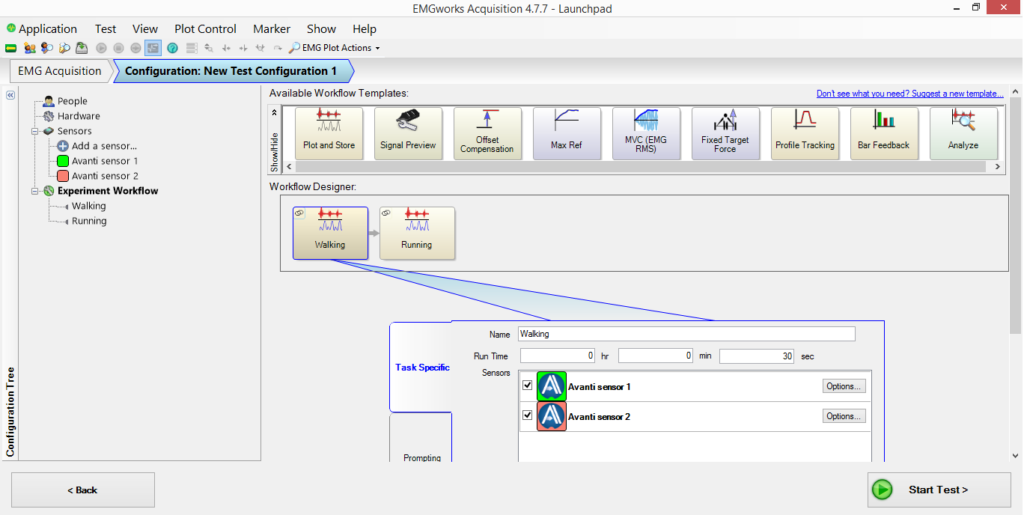
Task Name– Name of each workflow template.
Ex. If using multiple Plot and Stores, each one will have its own name. Suggested names would be the activity performed, such as ‘Walking’ or ‘Running’.
Task Number- The number counter associated with each run performed using a single Workflow Template.
Ex. Walking is Task #1. Running is Task #2.
Overall Rep Number– The number counter associated with each run performed while EMGworks Acquisition has been open.
Ex. You have two Plot and Stores. One named ‘Walking’ and one named ‘Running’. The protocol consists of 3 ‘Walking’ trials followed by 3 ‘Running’ trials. The Subject ID is ‘Subject A’. The 6 files will be named.
Subject_A_Walking_Rep_1.0
Subject_A_Walking_Rep_2.1
Subject_A_Walking_Rep_3.2
Subject_A_Running_Rep_1.3
Subject_A_Running_Rep_2.4
Subject_A_Running_Rep_3.5
EMGworks Analysis
The Workspace, Calculations and Plots are saved in the workspace folder as:
.ewp: Workspace file. Users can open an entire saved EMGworks Analysis Workspace by simply opening this file.
.emc: Calculation outputs
.emp: Plots generated from .emc or .hpf files
Data files are saved as:
.hpf: Raw data from EMGworks Acquisition
.shpf: Raw data from Android applications:
.emtx: File generated with the “Analysis” Workflow Template. This is used by the software to locate the .hpf file. It does not contain data.
Where is my data saved in EMGworks Acquisition?
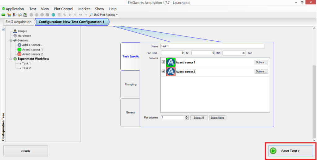
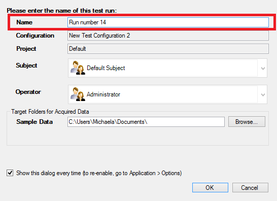
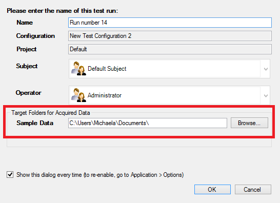
Data is saved in the location specified in the ‘Test Run Name’ window that appears after selecting ‘Start Test’. This dialog box allows users to change the file storage location prior to each data collection.
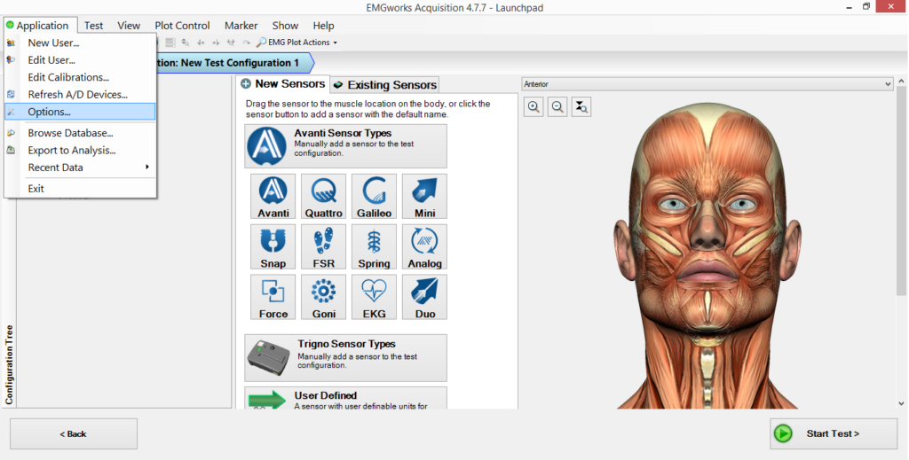
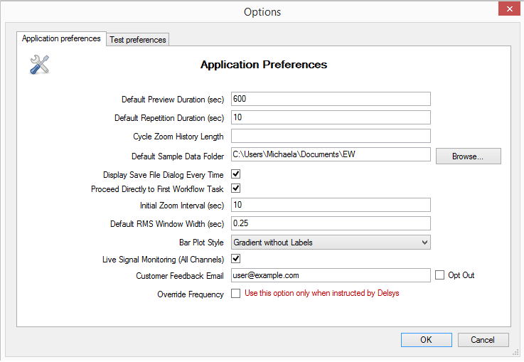
By default, the .hpf files will be saved in the users documents folder, however you can redirect this accordingly by going to:Application › Options… › Default Sample Data Folder › Choose new file storage location.
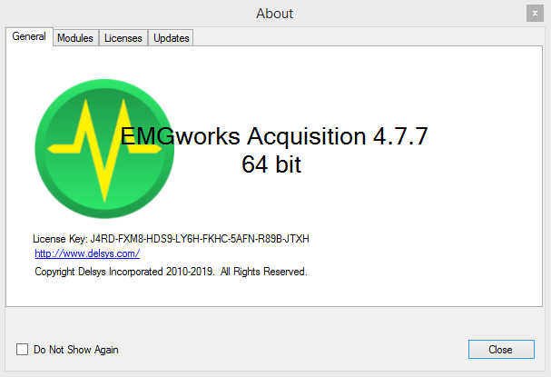
How do I find my EMGworks license key?
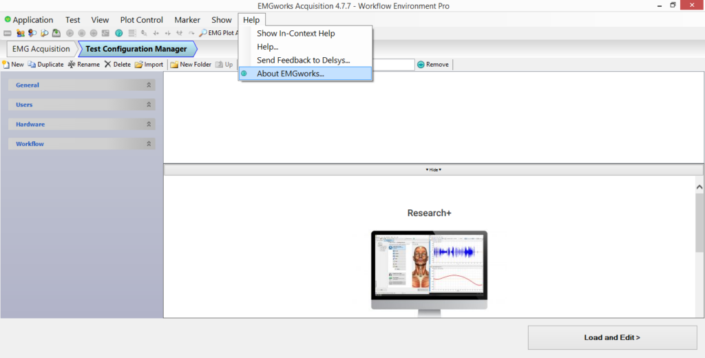
Open EMGworks Acquisition.
Select Help › About EMGworks
Your EMGworks license key will be the 32-digit alphanumeric code that appears below the logo
Which A/D cards will function with EMGworks?
Delsys is constantly seeking to expand its offerings for our clients, while maintaining the highest quality standards. At this time National Instruments is the preferred A/D card manufacturer. We support various National Instruments A/D cards; for details, please contact support@delsys.com or request Technical Support.
What causes the LINE INTERFERENCE and HI LED indicators to turn on?
If the EMG system specified in the Hardware Configuration has clipping and line interference outputs, these lights will illuminate in EMGworks when the signal is being clipped or there is line interference in the signal. If the EMG system specified in the Hardware Configuration does not have clipping and line interference outputs, these lights can be disabled by choosing Options from the Tools menu and un-checking the Display Clipping and Line errors check box in the Options dialog box. The control signals for the software indicators come from the Bagnoli 4/8/16 Main Amplifiers.
I have performed a calculation on my data and the resulting plot is blank. How can I display the traces?
This situation commonly occurs if the result of the calculation is only 1 datum point. It is not possible for the EMGworks graph tools to plot only 1 datum point, since at least 2 points are required to draw a line. The single datum point can be easily viewed by using the “gridview” feature in the “view “menu. Note that versions of EMGworks 3.6 and higher will display the X and Y coordinates of the datum point on the plot area.
I see varieties of files in the EMGworks workspace. Please explain the various types and their purpose.
Data Acquisition File Structure
Data Acquisition TESTS consists of one or more SETS, each of which can be executed once, or repeated multiple times. The repetition of a SET is referred to as a “REP”.
Files terminating in “*.emt” are the TEST files; these describe all the parameters associated with a TEST.
Files terminating in “*.emg” are raw data files acquired during a single “REP” (i.e. repetition) of a SET.
The minimum number of files generated during data acquisition is one file for the TEST parameters (*.emt) and one file for the one repetition of a data SET (*.emg). Multiple repetitions of a SET result in multiple files terminating with *.emg.
Example: A TEST consisting of two SETs, each repeated twice results in the following files:
“TEST.emt”
“Set1[Rep1].emg”
“Set1[Rep2].emg”
“Set2[Rep1].emg”
“Set2[Rep2].emg”
Data Analysis File Structure
All data analysis is performed within the context of a WORKSPACE. The WORKSPACE is a concept used to track all active data files and plots used during an Analysis session.
Files terminating in “*.ewp” are WORKSPACE files.
Files terminating in “*.emc” are data sets resulting from performing an EMGworks calculation. These files can be generated from raw data (*.emg files) or from other calculation outputs (*.emc files).
Files terminating in “*.emp” are plot files. Their function is to graph either *.emg files or *.emc files.
Example: A simple workspace that contains an imported TEST, with a single calculation and a single plot would consist of the following files:
“Workspace.ewp”
“Calculation.emc”
“Plot.emp”
Note that the raw TEST data terminates with *.emt and *.emg files. These files are needed by the WORKSPACE, but are generated during Data Acquisition and may not necessarily reside in the same location as the WORKSPACE files.
The error message “Inappropriate input array size” appears when exporting data from EMGworks to Matlab. How is this resolved?
Mathworks has acknowledged this as a bug in MATLAB 7.0 (R14) and MATLAB 7.0.1 (R14SP1). Their recommendation is presented below:
There are several known issues with the COM interface shipped with MATLAB 7.0 (R14) and MATLAB 7.0.1 (R14SP1). See the problem descriptions below for more information.Fixes for all of the problems listed below have been addressed in an updated version of comcli.dll. You should replace the current version in your MATLAB installation with this updated version. Here are the required steps:
If you have not already done so, upgrade to MATLAB 7.0.1 (R14SP1). The revised version of comcli.dll will work only with this version of MATLAB.
Quit MATLAB.
Rename the following file: $MATLABbinwin32comcli.dll (where $MATLAB is the MATLAB root directory on your machine) to$MATLABbinwin32comcli.dll.old.
Download the new file: comcli.dll and place it in the same directory mentioned in step 3.
Restart MATLAB
After restarting MATLAB, issue the following command at the MATLAB prompt: rehash toolboxcache.
Note that if you use MATLAB Compiler to deploy applications that use the COM Interface, you will have to package the revised comcli.dll separately. On the target machine, the revised comcli.dll should replace the original in $MCR_ROOTbinwin32.
Note that to use the “Export to MATLAB” feature, you need to run EMGworks with administrator privileges. An alternative approach is to run the “Load EMG” script within the MATLAB environment and import *.emg files directly.
Myomonitor automatic network configuration does not work on my PC. What are the possible reasons?
There are three possible reasons for this:
The network is already configured. In this situation, you already can establish connectivity and there is no need to configure the adapter again.
The Wireless Zero Configuration service is stopped. (You may also see error 1059.) In this case, go to Control Panel, choose Administrative Tools, choose Services, right click Wireless Zero Configuration, and choose Start.
Configuration is disabled on the wireless adapter. In this case, double click the adapter icon on the taskbar, click Change Advanced Settings, and navigate to the Wireless Networks tab. Make sure the item labeled “Use Windows to configure my wireless network settings” is checked.
How can I test my hardware connections outside of EMGworks?
You can test the board using the Test Panels in National Instruments Measurement and Automation (MAX).
Open MAX. In the configuration tree, select your A/D card (under NI-DAQmx devices). Click the “Test Panels…” button.
On the Analog Input tab, set the channel name to DevX/ai0, set the mode to On Demand, set the input configuration to RSE, and uncheck Auto-scale chart. Connect an EMG sensor to channel 1 on the amplifier and set the gain knob to 1k.
Press Start. At this point you should see the data responding if you tap one of the silver bars with your finger. The signal should be flat when the bars are shorted.
I have a data set in which some channels are EMG data and some channels are goniometer data. I would like to perform a RMS on the EMG data and leave the goniometer data untouched.
To do this, you can expand the data set in the workspace tree so that you can see the channels within it. Hold down Ctrl and select the channels on which you would like to perform a RMS by clicking them, then right click and choose Calculations->RMS. In the RMS window, the Applies To section will list these channels.
To plot the processed channels in conjunction with the unprocessed channels, expand the RMS calculation as well. Then Ctrl-click to select the processed channels from one data set and the unprocessed channels from the original data set. You can then right click and choose Plot. (This operation can also be done within the Plot->Create Plot wizard.)
I want to export my EMG data to Microsoft Excel, but Excel can only handle 65536 rows of data at a time.
Use the Subset calculation to split your data into smaller data series. Right click on the file in the EMGworks Analysis tree and choose Calculations->Subset.
Why does the data sampling frequency change when I do a windowed calculation?
Given the subset of data within one window, the calculation will produce a single data point (for example, the RMS of the data in this window for a windowed RMS). This is repeated for each window within the data set. This reduction of data points means that the sampling frequency changes.
How can I save my .emg or .emc data as a text file?
Select your data or calculation result in the workspace tree, then choose Tools->Export to CSV File. This will produce a comma-delimited text file which can be read by Excel and many other programs (including Notepad or other text editors).
Troubleshooting
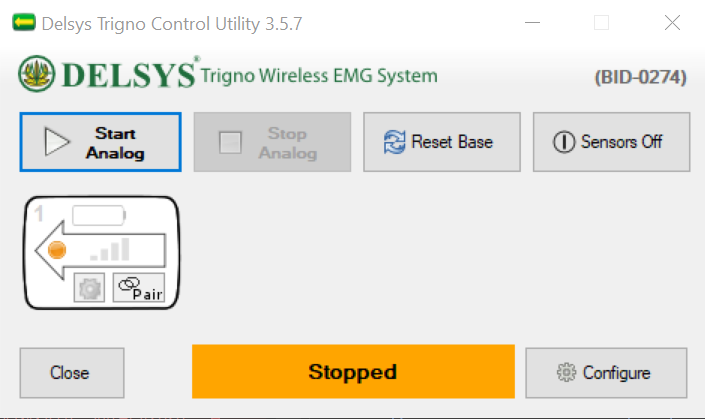
The Trigno Control Utility/EMGworks Acquisition Sensor Status Menu shows limited (<16) or no Sensor Icons. How can I resolve this?
Compromised Trigno Control Utility or Sensor Status interface.
Solution
Close all Delsys programs.
Open the Delsys Software Update Tool. This gets installed with your other Delsys programs and is located within C:\Program Files (x86)\Delsys, Inc.
Allow the Update Tool to query your base station information.
Click Reset Base Flash Memory.
Wait 5 seconds and close the Update Tool.
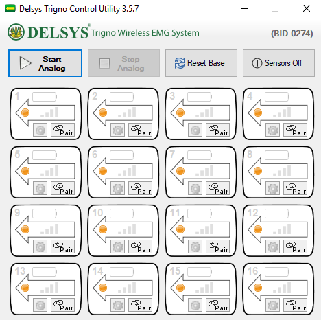
Open Trigno Control Utility or EMGworks Acquisition and confirm 16 sensor icons appear in the interface.
Proper Trigno Control Utility or Sensor Status interface.
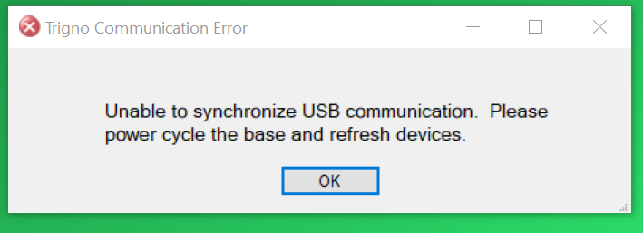
How can I fix the ‘Unable to synchronize USB communication’ error I received when opening the Trigno Control Utility or EMGworks Acquisition?
Solution
Close all Delsys programs.
Disconnect the Trigno Base Station’s power supply.
Wait 5 seconds and reconnect the power supply.
Open the Delsys program of your choosing.
If the problem persists:Please follow our firmware guide to ensure you’re running compatible versions of the Trigno software and firmware.
EMGworks Acquisition and/or the Trigno Control Utility is unable to open. What can I do to resolve this?
Solution
Go to the Windows Task Manager and make sure to close any instances of a Delsys program that may be running in the background.
Navigate to one or both of the following locations, depending on which ones exist on your PC:
Navigate* to the following location C:\Users\[username]\AppData\Roaming\Delsys, Inc\EMGworks
Delete all .XML files.
Navigate* to the following location C:\Users\[username]\AppData\Roaming\SensorBaseControl\SensorBaseControl
Delete all .XML files.
Re-attempt to open EMGworks Acquisition and/or Trigno Control Utility.
*The AppData folder on your PC may be hidden.To show hidden files and folders, follow the steps below:
Open File Explorer from the taskbar.
Select View › Options › Change folder and Search Options.
Select the View tab and, in Advanced settings, select Show hidden files, folders, and drives. Select Apply › OK
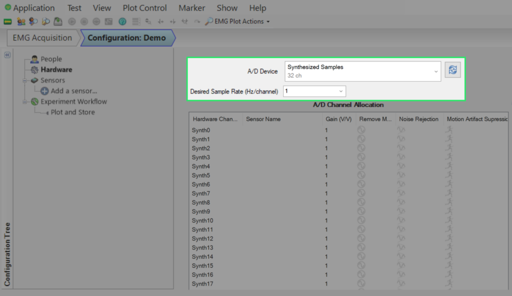
Why is my Trigno System not appearing as a hardware choice in EMGworks Acquisition?
Solution 1
Select the dropdown menu circled above and select Trigno Wireless System if possible.
If the Trigno Wireless System is not an option, please proceed to Solution 2.
Solution 2
Close the EMGworks program.
Disconnect the Trigno Base Station’s power supply.
Wait 5 seconds and reconnect the power supply.
Open EMGworks Acquisition and navigate back to Test Configuration’s Hardware tab.
Select Trigno Wireless System.
If still unavailable, make a new Test Configuration.
Solution 3
If the problem persists, please follow our firmware guide to ensure you’re running compatible versions of the Trigno software and firmware.
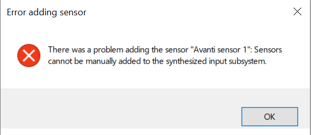
Why am I getting an ‘Error adding sensor’ message when trying to add a Trigno Sensor to a Test Configuration in EMGworks?
Solution
This error is a result of the Trigno Base Station not being selected or recognized in the Test Configuration. Follow the steps from Why is my Trigno system not appearing as a hardware choice in EMGworks Acquisition? to resolve.
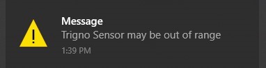
I am receiving a ‘Trigno Sensor may be out of range’ message. What does this mean and what actions, if any, should I take?
Solution
There are several instances that may prompt this message to appear, but it is mostly attributed to the first point below:
This message appears commonly at the beginning of setup while sensors are being turned on and paired in preparation for data collection.
This can be considered normal operating behavior.
A Trigno Sensor has either been moved out of range from the receiver or turned off (accidentally or purposefully).
If you’re actively streaming data, ensure you’re still collecting the expected signals.
If the signals you’re seeing in real-time are not expected, stop the collection and re-pair the sensor. Confirm its status in the Control Utility or Sensor Status window before starting again. Ensure you’re recording within the guaranteed range of the Trigno Base Station.