Trigno Base Station Support

Equipment Setup

Solution

The Trigno Sensors are required to be paired to a particular slot (1-16) or slots prior to running a data collection. The Trigno Base Station will remember the last paired sensors for each slot, requiring the user to simply turn on the sensors for future collections. They will automatically pair to the previously defined slot(s). If you need to change the sensor slot alignment or incorporate different sensors, then the pairing process will need to be followed, as outlined below.

Turning the Sensor On

Pairing the Sensors

Complete this cycle until all sensors are properly arranged and paired.

Pairing multi-channel sensors – Trigno Quattro, Trigno Galileo and Trigno Duo

By default, these sensors take up more than one of the 16 slots when paired due to the wireless bandwidth required to operate. The Quattro and Galileo Sensors occupy 4 slots, while the Duo occupies 2 slots. Other Trigno Sensors may have modes that increase their slot allotment from 1 to 2 or 4, although these are not by default. For full details on available modes, refer to the Trigno Wireless User’s Guide or specific sensor User’s Guide.

The pairing procedure is the same as above, however, the following rules apply:

  • 4-slot sensors can only be paired to slots 1, 2, 3 or 4.
  • 2-slot sensors can only be paired to slots 1, 2, 3, 4, 9, 10, 11, or 12.
  • When a sensor takes up more than one channel, the associated slots are outlined in blue.
This example shows 4 and 2-slot sensors paired and ready for use.

Solution

Ensure your base station has analog outputs. A base station with analog outputs will have (2) 68-pin connectors on its side, below the USB, Power and Trigger ports.

  1. Once turned on and paired, set each sensor to a mode that samples EMG at 1926 Hz. This will ensure analog outputs will be active when hitting ‘Start Analog’.
  2. To change sensor settings, click the located within the sensor icon, adjacent to the Pair button.
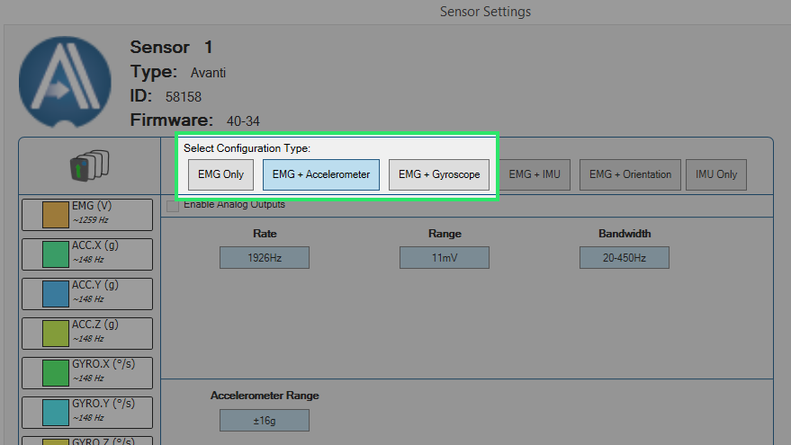
  3. Choose the appropriate mode. For EMG sensors, this can be done by selecting ‘EMG+Accelerometer’ or ‘EMG+Gyroscope’.

      • Users are not required to collect accelerometer or gyroscope data, this simply places the sensors in a mode where EMG analog outputs are supported.
      • The base stations 1-16 analog output connector will just contain EMG signals whereas the 1-64 analog output connector will contain EMG+ACC or EMG+GYRO signals.

Users should also be aware of the following details:

  • Analog outputs are supported for all Trigno Avanti Sensor types, except:
    • Trigno Galileo
  • All analog output signals are capped at a bandwidth of 500 Hz.
  • Delsys provides hardware solutions to convert the 68-pin connectors on the Base Station to open wire cables for screw terminal interfaces and BNC breakout boxes.

If you want to learn more about how to interface the Base Station’s analog outputs with your DAQ setup, please reach out to support@delsys.com.

Solution

The Delsys Trigger Module can be used to send out or receive both Start and Stop pulses for synchronization with 3rd-party systems. In this scenario, we will assume the 3rd-party system(s) will be responsible for triggering the Trigno System. Thus, the sync pulse will be generated and sent to the Delsys Trigger Module’s input BNC connectors – the top right (Start) and, if applicable, top left (Stop).

If you wish to have the Delsys Trigger Module send out a sync pulse for starting and/or stopping 3rd-party system(s), simply connect from the output BNC connectors. No other selections are required in the EMGworks software, by default the Trigger Module sends out start and stop sync pulses when the ‘Start’ and ‘Stop’ buttons are pressed in EMGworks Acquisition.

  1. Plug the Trigger Module’s connector into the Base Station’s trigger port The red dot on the cable’s connector should be facing downwards.
  2. Turn the Trigger Module on with the toggle switch. Illuminated light indicates Trigger Module is on.
  3. Ensure all BNC connectors are secured between the Trigger Module and 3rd-party systems.
  4. Navigate to the General settings of your Workflow Template tasks in EMGworks Acquisition. Most commonly, users will be working with the Plot and Store template.
  5. Depending on your desired trigger setup, choose whether you’ll be using a Start trigger, Stop trigger, or both.
  6. Click Start Test › Name test run › Okay › Start on recording screen.
  7. At this point, the system is armed but no data will appear. As soon as the 3rd-party trigger pulse is delivered to the Start input connector, data will stream.
  8. The recording will end when receiving a Stop trigger (if this option was selected). However, users can still allow the run to end based on the set Run Time or by simply hitting ‘Stop’ on the recording screen.

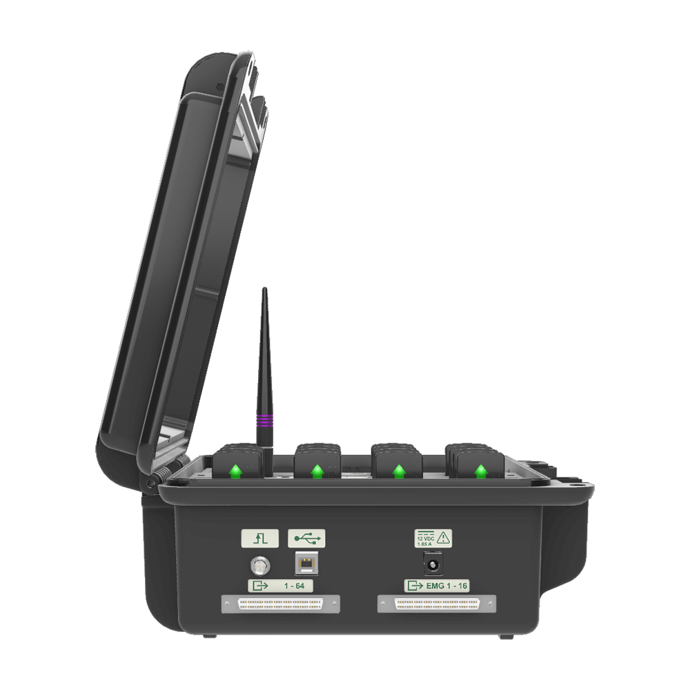
The Delsys Trigger Module does offer various edge settings and pulse width settings for handling incoming or outgoing synchronization pulses. For complete technical details please refer to the User’s Manual.

Software Update Tools

PC Firmware Update Tool

The PC Firmware Update Tool requires a Laird USB RF Adapter. Please contact support@delsys.com for assistance.

Trigno System Update Tool

Utility for updating Trigno Base Station firmware and Trigno Legacy sensor firmware.

Downloads

Video Tutorial